

XGM868i Gas Flowmeter

- Ultrasonic Flow Metering System Complete metering system for virtually any gas
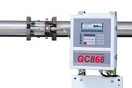
- Economical Compact Transmitter Creates no pressure drop, has no moving parts to collect debris and seldom requires maintenance
- Optional Dual-Channel Provides enhanced accuracy when measuring two paths on a single pipe
Overview
The XGM868i from Panametrics is a gas flow meter designed to measure the flow rate of almost any gas. It is suitable for measurement of vent gases, waste gases, biogases, hydrocarbon gases, vapor recovery and more. No pressure drop is caused by installation of the unit and it requires very little maintenance as it has no moving parts to collect debris. The meter is easily installed and provides reliable drift free operation. All this in a low cost transmitter.
Flow rate data can either be displayed locally or can be displayed on a remote system via an analog or digital communications link.
The gas flow meter can be installed directly at the flow measurement point as the electronic components are housed in a compact transmitter package. This simplifies the wiring of the instrument.
A dual channel model of the XGM868 gas flow meter is also available which allows single path measurement on two pipes or measurement of two paths on a single pipe.
Manufactured by: Panametrics
Model: XGM868i Gas Flowmeter
Services offered for this product
- Sales
- Rental
- Installation
- Calibration
- Maintenance
- IoT Cloud Compatible
Applications
Hydrocarbon gases
Fuel gases
Vent gases
Biogases
Digester gases
Waste gases
Incinerator air flow
Vapor recovery
Stack gases
Other gases
Specification
| Operation and Performance | |
| Fluid Types | Acoustically conductive gases |
| Pipe Sizes | 2 to 120 in. NB (50 to 3,000 mm) and larger |
| Pipe Materials | All metals. Consult RS Hydro for other materials |
| Flow Accuracy (Velocity) | ±1% to 2% of reading typical Accuracy depends on pipe size and whether measurement is one-path or two-path. Accuracy to ±0.5% of reading may be achievable with process calibration. |
| Repeatability | ±0.2% to 0.5% of reading |
| Range (Bidirectional) | -150 ft/s to 150 ft/s (-46 m/s to 46 m/s) |
| Rangeability (Overall) | 1500:1 |
| Specifications assume a fully developed flow profile (typically 20 diameters upstream and 10 diameters downstream of straight pipe run) and flow velocity greater than 3 ft/s (1 m/s). | |
| Measurement Parameters | Mass flow, standard and actual flow, totalized flow, and flow velocity |
| Electronics | |
| Flow Measurement | Transit time |
| Enclosures | • Standard: Epoxy-coated aluminum Type 4X/IP66 Class I, Division 1, Groups B,C&D Flameproof ISSeP 02ATEX008 II 2 GD EEx d IIC T5 IP66 T95°C • Optional: Stainless steel |
| Dimensions (h x d) | Standard: Size 8.2 in x 6.6 in (208 mm x 168 mm), Weight 10 lb (4.5 kg) |
| Channels | • Standard: One channel • Optional: Two channels (for two pipes or two-path averaging) |
| Display | Optional: 2 line x 16 character backlit LCD display, configurable to display up to four measurement parameters in sequence |
| Keypad | Built-in infrared, six-button keypad for full functionality operation |
| Power Supplies | • Standard: 90-260 VAC • Optional: 12 to 28 VDC, ±5% |
| Power Consumption | 20 W maximum |
| Operating Temperature | -40°F to 140°F (-40°C to 60°C) |
| Storage Temperature | -67°F to 167°F (-55°C to 75°C) |
| Standard Inputs/Outputs | Two 0/4 to 20 mA isolated outputs, 600 Ω maximum load |
| Optional Inputs/Outputs | All analog and digital I/O are available in special combinations. Consult GE for available option cards. • Two additional 0/4 to 20 mA isolated outputs, 1000 Ω maximum load • Two 4 to 20 mA isolated inputs, 24 VDC loop power • Two or four isolated, three-wire RTD (temperature) inputs, -148°F to 662°F (-100°C to 350°C), 100 Ω platinum • Two or four pulse or frequency outputs, optically isolated, 3 A maximum, 100 VDC maximum, 1 W maximum, from DC to 10 KHz maximum • Alarm relays: Two or four Form C relays; 120 VAC, 28 VDC maximum, 5 A maximum; DC 30 W maximum, AC 60 VA maximum |
| Digital Interfaces | • Standard: RS232 • Optional: RS485 (multiuser) • Optional: Modbus® RS485 or TCP protocol • Optional: Ethernet • Optional: OPC server • Optional: Foundation Fieldbus® |
| Data Logging | • Standard: None • Optional: Memory capacity (linear and/or circular type) to log over 150,000 flow data points |
| European Compliance | System complies with EMC Directive 89/336/EEC, 73/23/EEC LVD (Installation Category II, Pollution Degree 2) and transducers comply with PED 97/23/EC for DN<25 |
| Wetted Ultrasonic Flow Transducers | |
| Temperature Range | • Standard: -58°F to 302°F (-50°C to 150°C) • Optional (overall): -310°F to 842°F (-190°C to 450°C) |
| Pressure Range | • Standard: 0 psig to 2700 psig (1 bar to 187 bar) • Optional: 3480 psig (240 bar) maximum |
| Materials | • Standard: Titanium • Optional: Monel® or Hastelloy® alloys |
| Process Connections | Flanged and compression fittings |
| Mountings | Flowcell or cold tap |
| Area Classifications | • Standard: General purpose • Optional: Weatherproof Type 4X/IP66 • Optional: Explosion-proof Class I, Division 1, Groups B,C,&D • Optional: Flameproof II 2 GD EEx d IIC T6 |
| Transducers and flowcells for special applications are available. Consult GE for details. |
|