

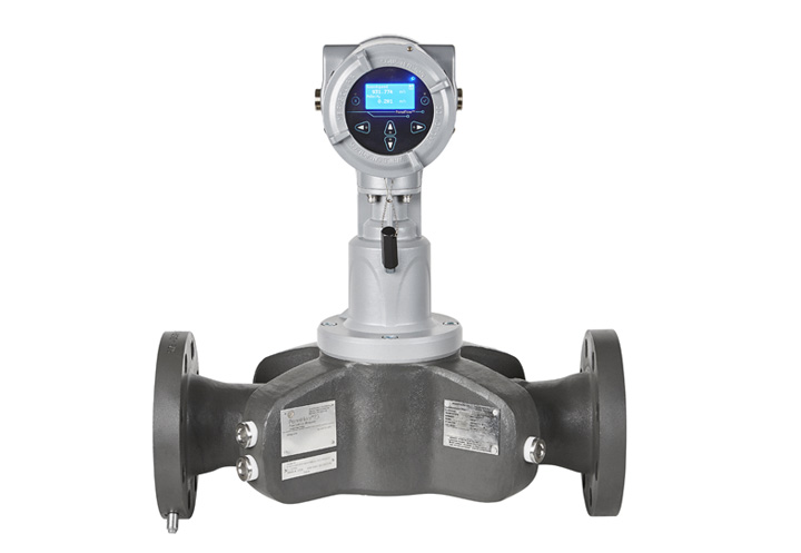
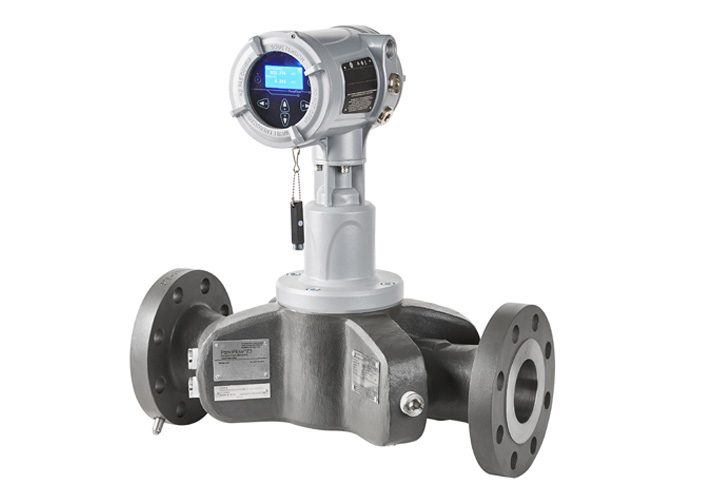
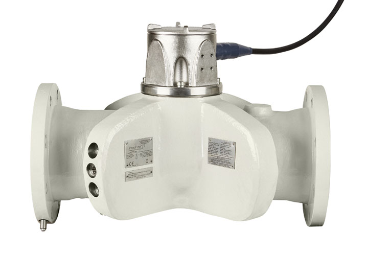
PanaFlow Z3 Panametrics Inline Ultrasonic Flow Meter
- Fast and Easy Installation The assembly work is done at the factory. The necessary components are already installed, so all the user needs to do is to bolt the end flanges into place.
- Bi-Directional Measurement No additional meters required
- No Moving Parts No loss of process control, no downtime, no expense from calibration, and optimization of assets.
Overview
The PanaFlow Z3 is a three-path, wetted ultrasonic flow meter that brings together all of the advantages of ultrasonic technology at a very affordable value. Unlike other flow measurement technologies, the PanaFlow Z3 does not require maintenance since it does not have any obstruction in the flow path that could clog the process line or moving parts to be damaged by the flowing fluid.
Also, due to the inherent nature of ultrasonic flow measurement, the PanaFlow Z3’s measurement is not affected by changing process conditions (temperature, pressure, and conductivity) and does not drift over time, which eliminates the requirement for periodic calibration. Without requirements for maintenance and calibration, the PanaFlow Z3 offers high performance with a low cost of ownership.
Manufactured by: Panametrics
Model: PanaFlow Z3 Panametrics Inline Ultrasonic Flow Meter
Services offered for this product
- Sales
- Rental
- Installation
- Calibration
- Maintenance
- IoT Cloud Compatible
Applications
Chemical
Petrochemical
Refining
Power generation
District energy/HVAC
Water/wastewater
Process control and monitoring
Allocation measurement
Batching and blending
Transfer lines
Cooling water lines
Pipeline metering
Loading/unloading
Plant utilities
Tank farms
Irrigation
Crude refined products
Specification
| Operation and performance | |
| Fluid types | Liquids: acoustically conductive fluids, including most clean liquids, and many liquids with small amounts of entrained solids or gas bubbles. |
| Flow measurement | Correlation transit time model |
| Accuracy | 3 to 24 in (80 to 600 mm)
2 in (50 mm)
Accuracy statement assumes measurement of a single phase homogenous liquid with a fully developed symmetrical flow profile passing through the meter (typically 10 diameters upstream and 5 diameters downstream of straight pipe run). Applications with piping arrangements that create an asymmetrical flow profile may require extended piping straight runs and/or flow conditioning for the meter to perform to this specification. |
| Calibration | All meters are water calibrated at ambient conditions and include a calibration certificate.
|
| Repeatability |
|
| Range (bidirectional) | -82 to 82 ft/s (-25 to 25 m/s) |
| Meter body/transducer system | |
| Meter body materials |
|
| Transducer system and material |
|
| Process fluid temperature range |
|
| Pressure range | Up to maximum allowable flange operating pressure at temperature per ASME B16.5 or EN1092-1 |
| Piping design |
|
| Transmitter | |
| Enclosures | Powder coated aluminum (copper free) or stainless steel (SS316) conformal coated |
| Classifications | US/CAN: Class I, Division 1, Groups B, C, D; *Maximum ambient temperature is 60°C (140°F when foundation fieldbus option selected) |
| Transmitter mounting | Local or remote mounting |
| Paths |
|
| Display | English 128 x 64 mono-color LCD display, configurable for single or dual measurement parameters |
| Keypad | Built-in magnetic, six-button, lockable keypad |
| Cable entries | ¾” NPT M20 adapters |
| Power supplies | Universal 100-240 VAC 50/60 Hz ±10% or 12 to 28 VDC (15W max, 7W typical) |
| Standard inputs/outputs |
|
| Optional inputs/outputs | Analog and digital I/O are available in specific combinations. See ordering information below for details:
|
| Digital interfaces |
|